Alarms and sensors, read as data on the bridge.
WaveBridge Data Acquisition Unit reads thirty digital inputs up to 300 V AC/DC and four analog inputs, selectable per channel. The results leave as NMEA 0183 over RS-485 and as Modbus TCP registers at once, set up from the unit’s web interface.
The parts of the ship that have no data port.
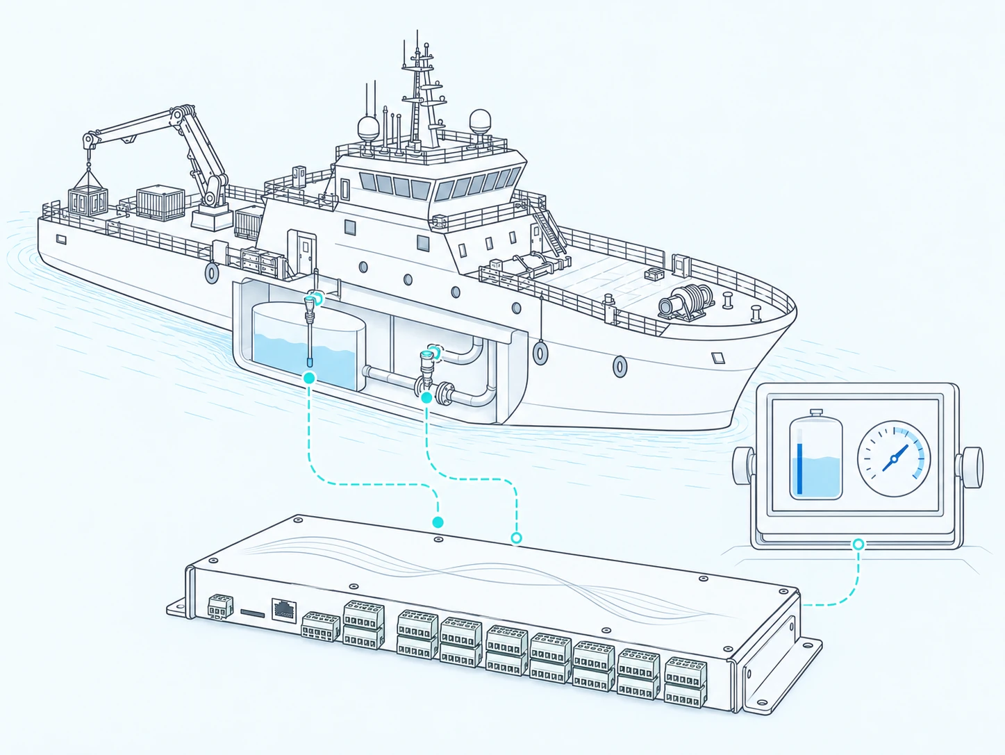
Tank and pressure, read directly
Analog sensors around the vessel are wired straight into the unit, and what they measure is carried up to the bridge as a value the watch can read.
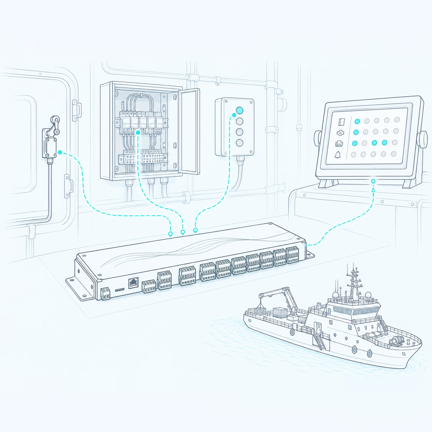
Switches, relays and contacts
Digital status lines are gathered on the unit's channels, so a position that was only a contact closure becomes something a monitoring system can show.
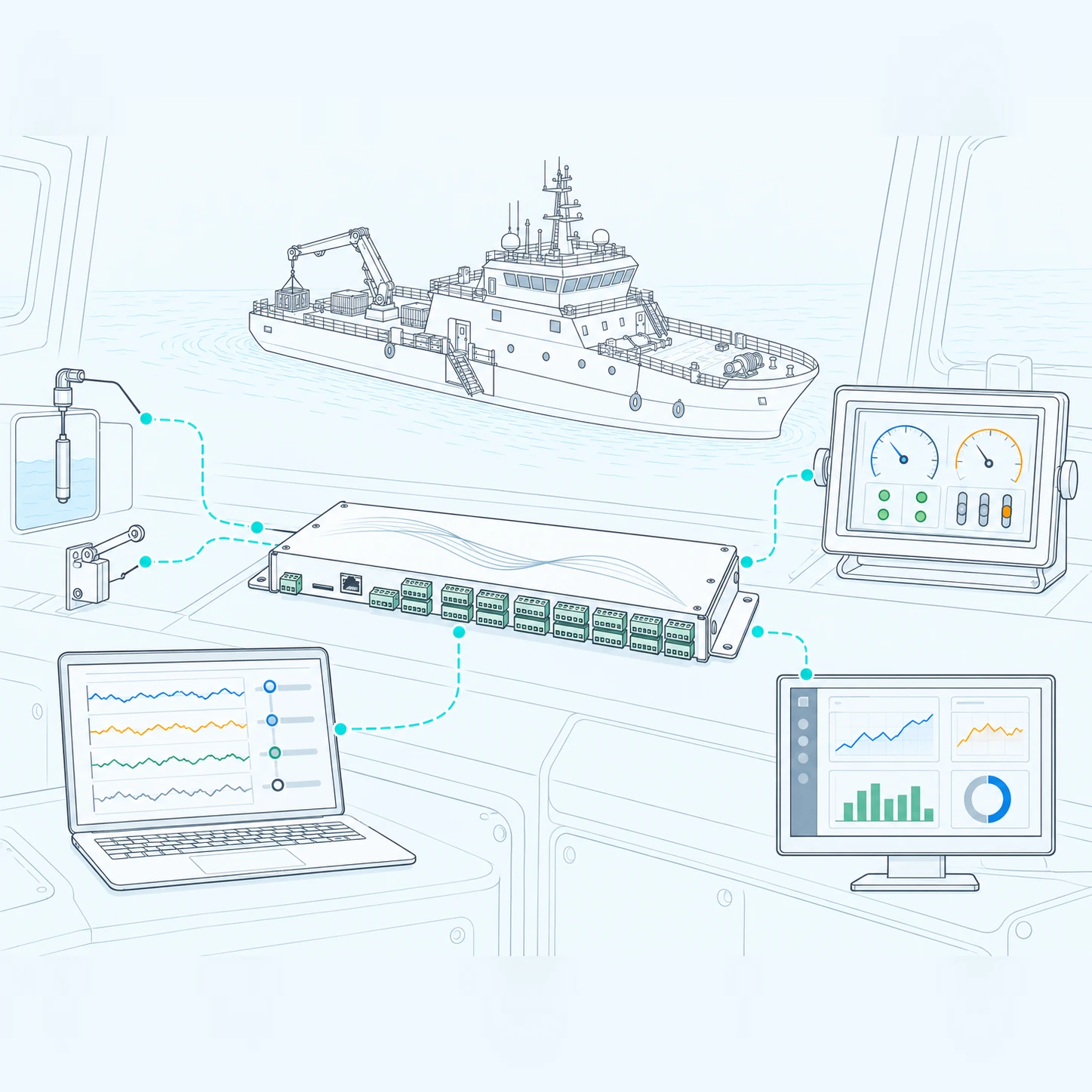
Set up in a browser
Channels are scaled and named from the built-in web interface, and the same measurements leave the unit as NMEA 0183 sentences or as Modbus TCP registers.
Key Benefits
Thirty digital inputs up to 300 V AC/DC, isolated in groups of five.
Four analog inputs, ±20 mA or ±15 V selectable per channel.
NMEA 0183 over full-duplex RS-485 and Modbus TCP in parallel.
Built-in web interface for thresholds, calibration and live monitoring.
Every input, one data stream
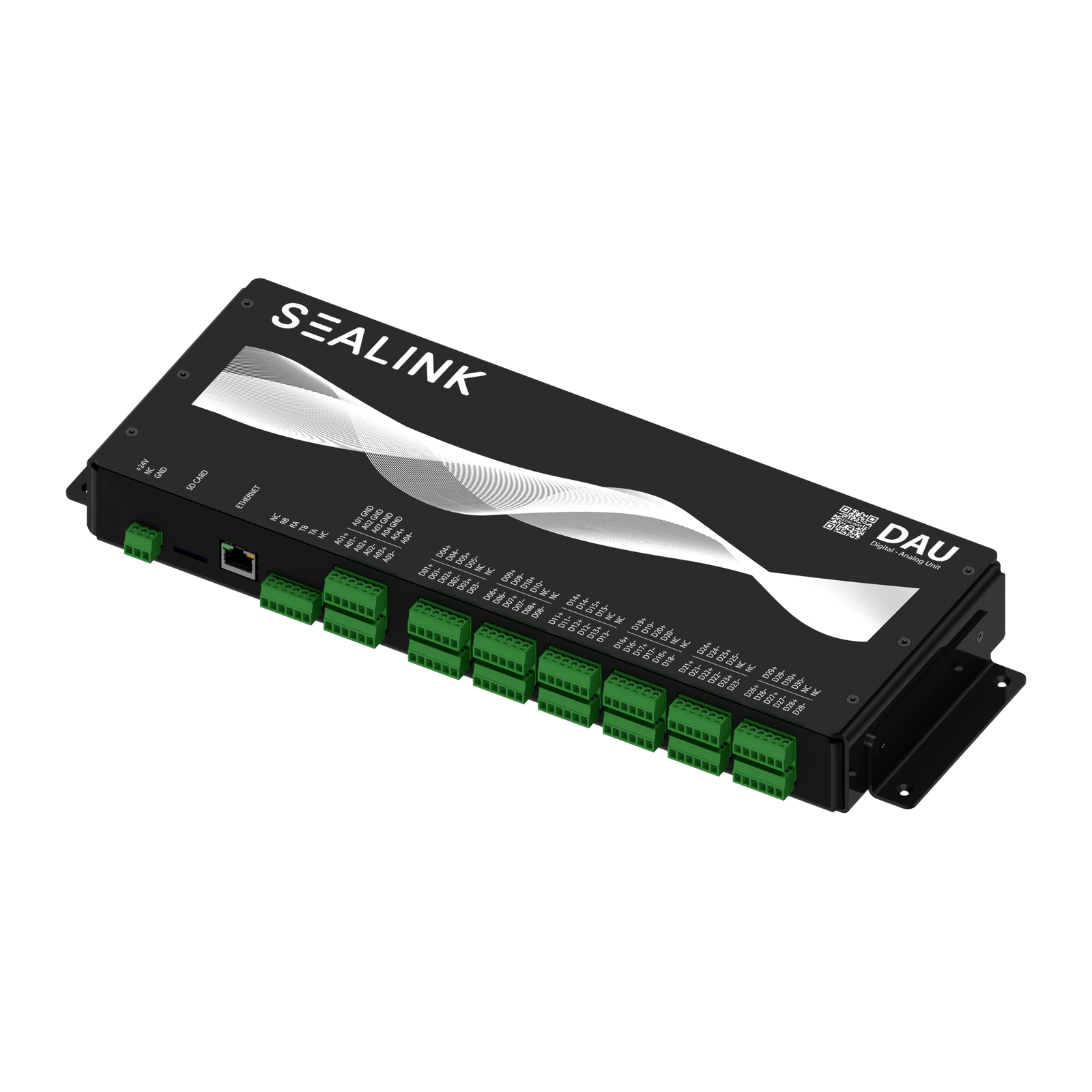
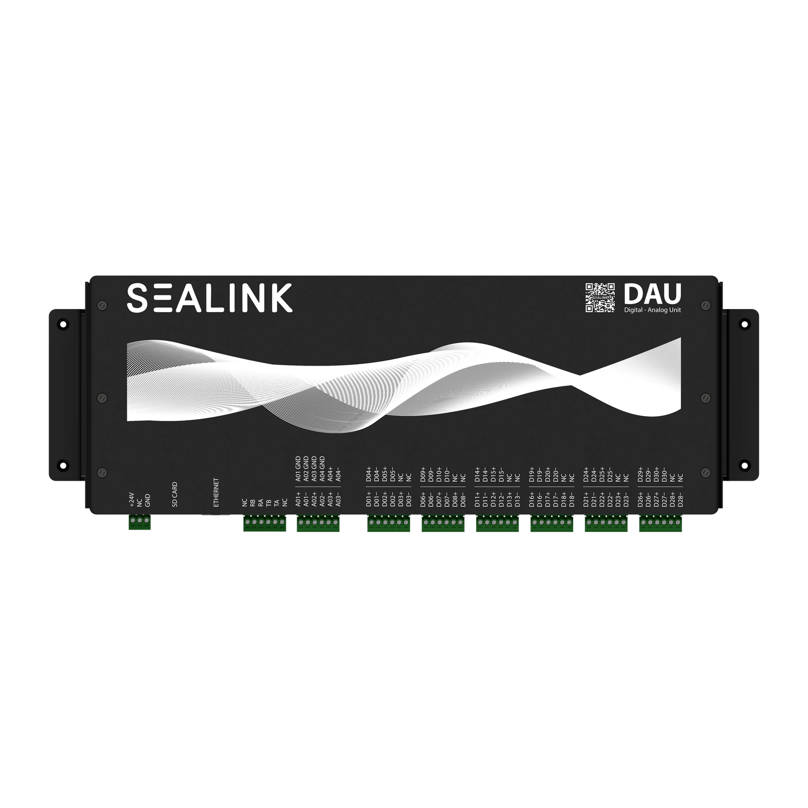
From contact closures to NMEA sentences.
WaveBridge Data Acquisition Unit turns 30 digital and 4 analog shipboard inputs into NMEA 0183 on RS-485 and into Modbus TCP registers. Thresholds, polarity, calibration and message identifiers are all set from its built-in web interface over Ethernet.
System Specifications
Digital inputs | 30 channels, up to 300 V AC or DC each, isolated in groups of five
Analog inputs | 4 channels, ±20 mA or ±15 V selectable, each with its own isolated ground
Serial output | NMEA 0183 on full-duplex RS-485
Network | Modbus TCP server and built-in web interface over RJ45 Ethernet
Firmware update | SD card slot
Supply | 24 V DC (9–36 V), 0.25 A maximum at 24 V
Environment | −20 °C to +55 °C, up to 80 % relative humidity, altitude to 5000 m
Interfaces & Integration
Digital channel settings | NO or NC mapping, AC or DC type, threshold voltage, live status and a Zero/One test on every channel
Analog channel settings | Voltage or current mode, input calibration, raw or user-corrected output value
Modbus registers | Analog values as 32-bit floats over two registers, digital channels as a 30-register array, read with function code 03
NMEA output | Custom digital and analog message identifiers, module identifier, decimal or hexadecimal data section
Daisy chain | A second unit's analog and digital inputs mirror into the slave register range, with a ready status register
Typical use | Alarm panels, tank and sensor loops and switchgear brought into bridge monitoring and recording systems
WaveBridge Data Acquisition Unit System Includes
1 × Data Acquisition Unit
WaveBridge DAU-430 main unit
15 × 6P Terminal Block
3.81 mm green female, for the digital and analog input groups
1 × 3P Terminal Block
3.81 mm green female, for the supply
Also supplied
Quick-start card, digital-manual QR card and the installation manual
Map Your Inputs
Alarm panels, tank and sensor loops and switchgear brought into bridge monitoring and recording systems.